Latitude 7300 Teardown Removal Guide for Customer Replaceable Units (CRUs)
Summary: This article is a guide to safe removal and replacement of the parts of a Latitude 7300 that Dell considers safe and easy for anyone to attempt.
Symptoms
These guides take you step by step through the safe removal of the customer replaceable unit (CRU) parts of a Latitude 7300. CRUs are the parts of the computer that should not need an engineer to remove or replace. The guides also include figures to reference what is involved.
Table of Contents:
Cause
Not applicable
Resolution
Removal Guide
If these guides do not cover what you are looking to do, then reference your System Manual.
The article below provides information about safe practices to consider before working with electrical equipment.
Removal Instructions
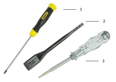
| 1 | Small Phillips head screwdriver | 2 | Plastic scribe |
| 3 | Small flat head screwdriver |
-
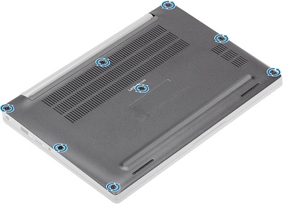
Pre-removal instructions before removing the main access panel:
-
During installation or removal of any hardware, always ensure that all data is backed up properly.
-
Disconnect any telephone, network, or USB cables from the computer.
-
Disconnect the computer and all attached devices from their electrical outlets.
-
-
Loosen the eight captive screws that secure the main access panel to the chassis.
-
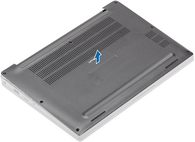
Use a plastic scribe (or some other probe that will not damage the plastics) to [1] to pry up the main access panel along the indent points near the hinges, then pry along the edges between the cover and the chassis to separate the main access panel from the computer [2].

-
Lift the main access panel off of the computer.
-
Pre-removal instructions before removing the battery:
-
During installation or removal of any hardware, always ensure that all data is backed up properly.
-
Disconnect any telephone, network, or USB cables from the computer.
-
Disconnect the computer and all attached devices from their electrical outlets.
-
Remove the System Cover.
-
-
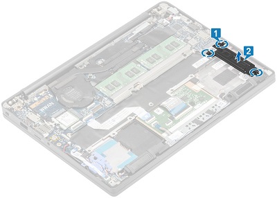
Pull up on the tag on the battery cable to remove the cable from the connector on the motherboard [1].
-
Loosen the captive screws, two screws for a 4-cell and one screw for a 3-cell battery [2].

-
Lift and remove the battery out of the computer [3].
-
Pre-removal instructions before removing the memory DIMM:
-
During installation or removal of any hardware, always ensure that all data is backed up properly.
-
Disconnect any telephone, network, or USB cables from the computer.
-
Disconnect the computer and all attached devices from their electrical outlets.
-
Remove the System Cover and Battery.
-
-
Pull the metal clips on either side of the DIMM away from each other to have the memory pop up in the connector [1] and then pull it out of the connector [2].

-
Repeat for any additional memory installed.
-
Pre-removal instructions before removing the solid-state drive (SSD):
-
During installation or removal of any hardware, always ensure that all data is backed up properly.
-
Disconnect any telephone, network, or USB cables from the computer.
-
Disconnect the computer and all attached devices from their electrical outlets.
-
Remove the System Cover and Battery.
-
-
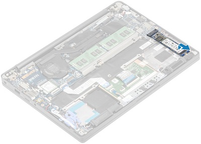
The SSD is located to the right of the battery. Loosen the three captive screws that secure the SSD bracket to the palm rest [1] and then remove the bracket from the computer [2].
-
The SSD card pops up at an angle from the chassis, and you can pull it out of the connector and the computer.
-
Pre-removal instructions before removing the SIM card:
-
During installation or removal of any hardware, always ensure that all data is backed up properly.
-
Disconnect any telephone, network, or USB cables from the computer.
-
Disconnect the computer and all attached devices from their electrical outlets.
-
-
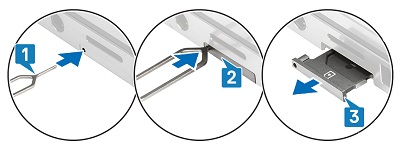
Straighten out a paperclip or use the SIM card removal tool to insert into the pinhole on the left side of the SIM card tray [1].
-
The card tray should partially eject from the side of the computer [2].
-
Grip the tray and pull it the rest of the way out of the computer [3].
-
Pre-removal instructions before removing the SD memory card:
-
During installation or removal of any hardware, always ensure that all data is backed up properly.
-
Disconnect any telephone, network, or USB cables from the computer.
-
Disconnect the computer and all attached devices from their electrical outlets.
-
-
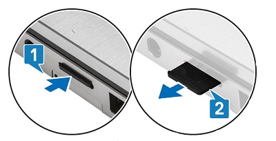
Press and release the SD card in the slot for it to partially pop out of the side on your computer [1].
-
Grip the card and pull it the rest of the way out of the slot [2].
-
Pre-removal instructions before removing the WLAN card (WiFi, wireless):
-
During installation or removal of any hardware, always ensure that all data is backed up properly.
-
Disconnect any telephone, network, or USB cables from the computer.
-
Disconnect the computer and all attached devices from their electrical outlets.
-
Remove the System Cover and Battery.
-
-
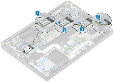
The WLAN card is below and to the left of the computer fan. Remove the single screw [1] that secures the WLAN card bracket to the chassis and remove the bracket from the computer [2].
-
Disconnect the antenna cables from the card [3] by lifting up the press stud connectors until they pop off and lift the card out of the connector [4] and the system.
-
Pre-removal instructions before removing the WWAN card (3G, cellular):
-
During installation or removal of any hardware, always ensure that all data is backed up properly.
-
Disconnect any telephone, network, or USB cables from the computer.
-
Disconnect the computer and all attached devices from their electrical outlets.
-
Remove the System Cover and Battery.
-
-
The WWAN card is above the WLAN card, remove the single screw [1] that secures the WWAN card bracket to the chassis and remove the bracket from the computer [2].

-
Disconnect the antenna cables from the card [3] by lifting up the press stud connectors until they pop off and lift the card out of the connector [4] and the computer.
If you require further assistance, contact Technical Support.
| Contact Us |