Article Number: 000223081
PowerVault ME4, ME5: Investigating power supply failure
Summary: PowerVault administrators must inspect and confirm electrical power is available to the PCM or PSU and the rocker switch on each PSU or PCM is set to on position before contacting Dell technical support to report a faulted power supply. ...
Article Content
Instructions
- Investigating reported power supply failure on PowerVault ME series
- Link to PowerVault ME series owners manual documentation
- Using power supply status LEDs to determine the nature of the fault
- Contacting Dell technical support
Investigating a reported power supply failure event
Note: If the power supply failure event has been resolved due to the power source to the enclosure being restored. PowerVault ME5 systems administrators may need to acknowledge the alert in PowerVault Manager. No further action is required.
PowerVault administrators may observe events relating to a power cooling module (PCM) or power supply unit (PSU) not operating, providing redundancy or reporting a fault. There may not be a fault with the PCM or PSU.
In event of loss of electrical power to a power supply, PowerVault ME5 Series arrays will report the following alerts in PowerVault Manager.
- The power supply is not receiving any input power
- The power supply is not supplying a DC voltage.
When investigating the reason behind PCM or PSU alerts consider the following possible causes:
1. Has there been a recent power outage at the location where the PowerVault ME unit is located?
- Were multiple devices in the rack impacted by power outage?
- Event logs from other devices within the rack, such as Dell PowerEdge iDRAC event logs may indicate corresponding loss of power to other devices in the rack. Check power is available to other devices.
- Where PowerVault ME has cable connections to redundant ethernet or fiber channel switches, administrators may observe management or host ports down when the same power source used by switches or directly connected hosts are lost.
- Where an uninterruptable power supply (UPS) or standby generator is used power may continue to be available to one PCM/PSU but not the other.
- Check with on site personnel if a power outage did occur at the location or if the site devices are running on a fallback generator or backup UPS.
2. Where rack Power Distribution Units (PDU) are used confirm the PDUs are functioning and receiving power.
- Due to redundancy or site power load balancing requirements some sites use 3 phase power or connect each PDU in the rack to a different electricity supplier or generator source. Confirm that all power sources to the PowerVault ME are operational.
- Where rack PDUs can be remotely managed use the PDU monitoring logs to confirm the PDU is not faulted and power is enabled for outlets used by the PowerVault ME units.
- Confirm rack PDUs are not being loaded beyond the manufacturers rating. Check the PDU vendors documentation and if overload is suspected work with your site electrician to measure and take steps to redistribute the load.
- Site administrators can use Dells Enterprise Infrastructure Planning Tool to calculate power and cooling requirements.
3. Where there has been recent site maintenance or maintenance within the rack with the PowerVault ME array ensure power supplies are still connected to a known good power source and the rocker switch on each power supply is set to the on position.
4. Consider what are site environmental conditions like in the location where the PowerVault ME enclosure is located?
- Where this fault has occurred as a consequence of fire or flooding or other malfunction in the datacenter or server room administrators must resolve these conditions before proceeding.
- Environmental requirements to operate the PowerVault ME are listed under the Technical specifications section in the owners guide manuals linked below.
5. Each power supply has LEDs, these help on-site personnel determine the source of the issue.
- Refer to the owners manual or section further down this article that describes interpreting the LEDs state.
6. When replacing failed power supplies, replace with the same 80 PLUS® efficiency rating as the original.
- If there is a mismatch PowerVault ME will report a PSU or PCM being in a degraded state after replacement.
- To determine which PSU type is being used, open an SSH session to the ME array and run the command
show power-suppliesand use the chart below to lookup the Part Number or else look for the 80 PLUS® label on the physical power supply unit.
# show power-supplies
Encl Id   Serial Number            Part Number Name          Firmware Version  Health
------------------------------------------------------------------------------------------
0    0    CN03PD98FCG0015J00NIA00  3PD98       PSU 0, Left   033D              OK
0    1    CN03PD98FCG0015J00OMA00  3PD98       PSU 1, Right  033D              OK
------------------------------------------------------------------------------------------
Success: Command completed successfully. (2024-03-13 08:58:43)
#
This table lists power supply part numbers and corresponding 80 PLUS® power efficiency used on PowerVault ME series. The difference occurs in some regions due to implementation of EU ErP Lot 9 regulation. Systems that shipped prior to implementation continue to use the original specification PCM/PSU when replacing failed parts.
-
PowerVault ME enclosure type
Dell Part Number 80 PLUS® Part Description Comments 2U chassis DYJW5 
Power Supply, 580 Watts, Platinum, With LED, 2U, Version 3 Do not intermix with Gold rated power cooling modules (PCM). NKVWF 
580 Watts, With LED, Power Supply, 2U 0VMRF 
580 Watts, With LED, Power Supply, 2U 3PD98 
580 Watts, With LED, Version 2, Power Supply, 2U 5U 84 chassis 0R4C4 
Power Supply, 2200 Watts, Titanium, 5U84, Version 4 Do not intermix with Platinum power supplies (PSU). KG1JH 
Power Supply, 2.2KW, 5U84, V2 6JN28 
2200 Watts, 5U84, Version 3, Power Supply
Note:Mixing different PCM/PSU part numbers is ok provided 80 PLUS® efficiency rating matches across both PSUs..
The Dell owners manual contains the instructions to replace parts on your PowerVault ME array. To replace the power supply look for the section "Customer-replaceable units (CRUs)"
Note: Administrators troubleshooting PowerVault ME5012 and ME5024 systems that use 48V DC power cooling modules (PCM) must refer to the Cabling Instructions for a DC Power Cooling Module guide for troubleshooting and servicing information.
Using PowerVault LEDs state to determine the fault
Note: The power cooling module provides power and cooling fans to 2U units.

Figure 1. ME4 series rear 2U chassis PCM location and orientation.

Figure 2 - AC Power cooling module for 2U chassis PowerVault ME series
-
Power cooling module LED states (2U chassis) PCM OK
(Green)Fan Fail
(Amber)AC Fail
(red)DC Fail
(Amber)Status Off Off Off Off No AC power on any PCM Off Off On On No AC power on this PCM only On Off Off Off AC present; PCM working correctly On Off Off On PCM fan speed is outside acceptable limits Off On Off Off PCM fan has failed Off On On On PCM fault (over temperature, over voltage, over current) Off Blinking Blinking Blinking PCM firmware download is in progress Blinking Off Off Off Both controller modules are missing.
Power Supply Unit (PSU) status LEDs location for ME5084, ME4084 & M484 enclosures
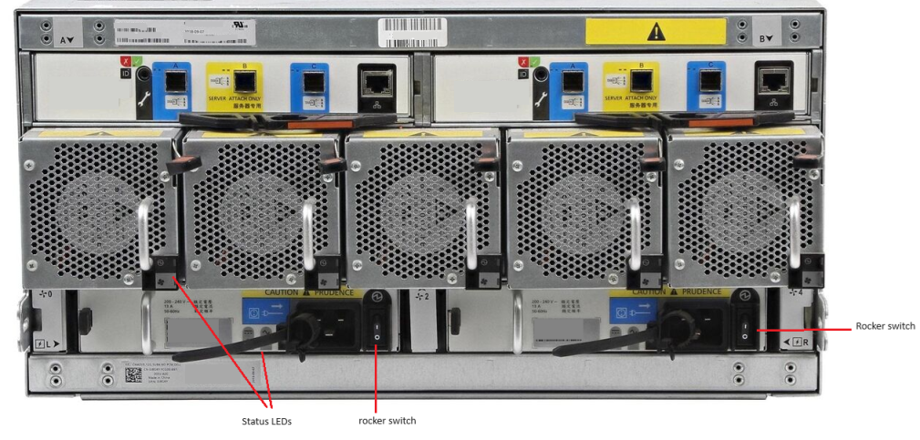
Figure 3. 5U84 chassis rear view showing PSU position

Figure 4. Close up view of a 5U84 chassis power supply
-
5U84 chassis PSU LED states CRU Fail
(Amber)AC Missing
(Amber)Power
(Green)Status On Off Off No AC power to either PSU. On On Off PSU present, but not supplying power or PSU alert state. (usually due to critical temperature) Off Off On Mains AC present, switch on. This PSU is providing power. Off Off Blinking AC power present, PSU in standby (other PSU is providing power). Blinking Blinking Off PSU firmware download in progress. Off On Off AC power missing, PSU in standby (other PSU is providing power). On On On Firmware has lost communication with the PSU module. On — Off PSU has failed. Follow procedure in owners manual “Replacing a PSU”.
To contact Dell technical support use the following URL: https://www.dell.com/support/incidents-online/ContactUs
1. List the outcome of troubleshooting steps or results of inspection already performed to isolate the fault.
2. Where possible collect the support bundle from the PowerVault ME array
Additional Information
Note:While power redundancy is degraded host write IO performance may be slower when write-back cache is set to write-through mode.
Article Properties
Affected Product
ME Series, OEMR ME40XX and ME4XX, Dell EMC PowerVault ME4012, Dell EMC PowerVault ME4024, Dell EMC PowerVault ME4084, Dell EMC PowerVault ME412 Expansion, Dell EMC PowerVault ME424 Expansion, Dell EMC PowerVault ME484, PowerVault ME5012
, PowerVault ME5024
...
Product
PowerVault ME5084
Last Published Date
15 Mar 2024
Version
3
Article Type
How To